Why multi-lane sites behave differently from a single-lane entrance
One barrier gate, one camera, one loop: the plate is read, a dry contact closes, the arm lifts, the loop holds the arm open until the car has passed. That sequence is well understood, and most single-entrance sites work with it. Add a second lane — or a lane that serves both entry and exit — and the failure mode changes completely.
The problems that appear on multi-lane sites are rarely camera problems. They are lane-plan problems: the queue backs onto the public road, drivers switch to the slow lane and cross the detection zone of a neighbouring camera, one vehicle generates both an entry and an exit record, the parking system cannot match a plate to a fee, or a second car slips through behind the first. Every one of those is decided by three things — how the cameras are distributed across the lanes, how many control outputs each lane owns, and in what order the camera, loop, arm and lane indicator act.
This guide is written for the stage that comes before a quotation: counting lanes, allocating cameras, planning relay and network wiring, sequencing the passage, and commissioning the site so that a four-lane car park behaves like one system instead of four unrelated gates.
Step 1 — Count lanes, directions and peak arrivals before choosing any hardware
Start with a simple table of the site, not with a product list. The number of lanes and the peak arrival rate decide the motor, the arm, and how many cameras the site really needs.
- Lanes and directions: one entry lane, one exit lane, or a single shared lane that handles both directions (common at residential compounds and small commercial buildings).
- Peak arrivals per hour: a residential compound might see 60–150 entries in the evening peak; a shopping centre or business park often sees several hundred across its peaks. Peak rate, not daily total, sizes the equipment.
- Queue space before the lane: if a car cannot stand clear of the public road while the barrier cycles, the lane needs a faster operator and a shorter decision path, not a longer arm.
- Vehicle mix: cars only, or cars plus light commercial vehicles and occasional trucks. Mixed traffic changes lane width, arm length and clearance height.
- Who pays: subscribers only (no payment devices), or visitors and short-stay parkers who need a payment step before the exit lane releases.
A useful rule for early planning: one detection camera per direction per lane is the layout that fails least often, because every vehicle crosses exactly one detection zone, and every record belongs unambiguously to one lane and one direction. Anything that departs from that rule needs a reason you can write down.
Peak throughput also determines whether you need a standard operator or a fast one. If a lane must serve more than roughly 600–900 vehicles per hour, the arm cycle time — not the recognition speed — becomes the bottleneck, and a fast DC brushless operator is the correct choice; the trade-offs are set out in our high-speed barrier gate guide. Lane geometry, arm length and clearance are covered in the boom arm length guide.
Step 2 — Camera allocation: one camera per lane, or one camera for two lanes?

Sharing one camera between two lanes is technically possible and regularly proposed to save cost. It works only when a short list of conditions is true:
- The camera reads both approaching and departing traffic reliably (multi-frame recognition, forward and backward capture).
- The two lanes are close enough, and the camera angle shallow enough, that both plates fall inside the recognition area with margin — not on the edge of the frame.
- Peak traffic never brings two vehicles from different lanes into the capture zone at the same time, or the software can separate them by direction.
- The site accepts that a single camera failure stops both lanes.
Where any of those conditions is doubtful, the practical answer is one camera per lane per direction. The additional channel is also what makes a lane independent: a lane can be taken out of service for maintenance without dropping its neighbour.
Two details decide recognition quality more often than the camera model. First, triggering: a camera triggered by a ground loop captures the vehicle at a known, consistent position, while pure video triggering depends on the software's vehicle detection. Second, the plate format: a site that receives foreign or temporary plates needs cameras whose recognition library covers those formats — check that before comparing recognition percentages. Our LPR camera series reads forward and backward plates, supports loop or video triggering, and is specified at up to 99% recognition success rate in good lighting conditions; the selection criteria are explained in the LPR camera guide.
Step 3 — Control outputs: how many relay channels does each lane need?
This is where multi-lane projects are most often under-specified, and where a two-channel controller suddenly becomes a change order. Count the signals, then check the hardware.
- Open command (mandatory): a dry contact (NO/COM) from the camera or from the lane controller to the gate board's OPEN input. Pulse length is typically set to a fraction of a second — long enough to trigger, short enough to avoid a double command.
- Close or stop command (site dependent): needed where the software, not the loop, ends the cycle — for example on an exit lane using a payment result to release the arm.
- Status feedback (recommended): arm open, arm closed or fault, reported back over a serial or network interface, so the software knows whether a lane is actually available.
- Loop / safety input (mandatory): the presence loop's output wired to the gate's safety input, so the arm cannot close while a vehicle is under it.
- Lane indicator or display: red / green signal and, where fitted, a message display or voice prompt for visitors.
If an access controller sits between the camera and the gate, the camera talks to the controller over a card-reader protocol such as Wiegand, and the controller owns the relay to the gate. That is a common architecture on sites that also use cards, tags or intercoms, and it moves the decision logic away from the camera — worth stating explicitly in the quotation so that responsibilities are clear.
Our LPR camera and parking controller communicate over RS232/RS485 or TCP/IP and can drive barrier gates directly, including third-party gates; the wiring methods themselves — relay, serial and network — are compared in the LPR-to-barrier integration guide.
Step 4 — Entry/exit pairing, anti-passback and shared lanes
On any site with a fee or a space count, matching an exit read to an entry read is the function that matters. Three design points follow from it.
- One lane, one direction: where entry and exit lanes are separate, every camera knows its direction, and pairing is a database operation with a timestamp.
- Shared bidirectional lane: a single lane used in both directions needs either two cameras (one facing each way) or a camera that captures front and rear plates, plus direction logic. Without direction logic, the same vehicle can generate two events minutes apart and close its own record.
- Anti-passback: if the tariff depends on one vehicle entering once, the software must refuse a second entry for a plate already inside. This is a software rule, but it only works if records are reliably paired — which is why camera allocation and direction logic come first.
Anti-passback is also the electronic half of tailgating prevention. The physical half — arm height, loop length, closing logic, signage and enforcement — is covered in the tailgating prevention guide.
Step 5 — Loops and lane indicators: the sequence that keeps traffic moving
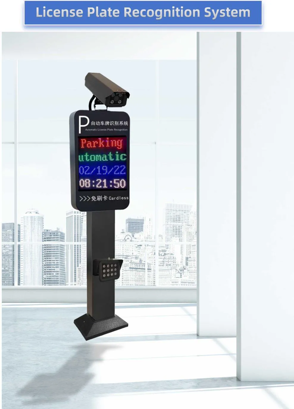
On a busy lane, the difference between smooth traffic and constant intervention is the order in which five things happen. A sequence that works on most sites looks like this:
- The vehicle enters the detection loop in front of the barrier; the loop trigger tells the camera a vehicle has arrived.
- The camera reads the plate and sends the plate to the software or controller.
- On an authorised result, the relay pulse opens the arm; the lane indicator turns green.
- The vehicle crosses the loop under the arm. That safety loop holds the arm open until the vehicle has cleared it, and the auto-close timer starts only after the loop releases.
- The free-exit loop beyond the arm confirms the lane is clear; the arm closes and the indicator returns to red.
Two configuration mistakes account for a large share of complaints. First, the auto-close time is set short and the arm starts down while the vehicle is still crossing — the fix is loop-controlled closing, not a longer time. Second, the loop layout only detects vehicles at the camera and omits the presence loop under the arm; that layout cannot prevent a closing arm hitting a car or a trailer. Loop sizing, wiring and detector settings are covered in the vehicle loop detector guide.
Where the site must allow a continuous stream at peak, some systems switch the lane to a normally-open mode for a fixed window, with the loop logic still protecting the arm. That mode is useful, but it should be a deliberate, time-bounded setting — not a workaround for a slow lane.
Step 6 — Network, power and software layer
Once more than two lanes are involved, the network stops being an afterthought. Write down, before installation:
- An IP plan: a fixed address for each camera and controller, outside the DHCP range used by office equipment, so a leased address never moves a lane.
- Server placement: local server or cloud. A cloud-managed platform removes the on-site computer, but the lane must still work if the internet link drops — check the offline behaviour of the system, ideally an on-board allowlist so authorised vehicles still pass.
- Cabling: network cable runs, PoE availability, and whether camera positions can be reached by conduit without exceeding the practical cable distance of the link.
- Power: a dedicated circuit for the lane equipment, and where possible a UPS for the controller and network gear so an outage does not leave a lane locked.
- Time: cameras and server synchronised to the same time source; timestamps are evidence in a dispute over an entry time or a fee.
Our own LPR system runs on a Linux-based controller with RS232/RS485 and TCP/IP interfaces and offers cloud API access for remote management; the camera and the controller can be supplied as one package with the barrier gate, so the interfaces are known to match before the site is cabled.
Step 7 — Site conditions that decide the hardware
- Lane width and arm length: the arm should block the lane, not the pavement; where a single arm cannot span the lane, a master-and-slave two-gate arrangement is a standard solution.
- Lighting: if the sun faces the camera at the same hour every morning, plan a shade or an alternative mounting position; recognition in low light depends on the illumination built into the camera.
- Shelter and drainage: cameras and controllers need protection from direct rain and standing water; raised plinths and IP-rated housings are cheaper than replacing units.
- Ground works: cutting loops means saw-cutting and resealing the surface — plan the loop positions with the camera positions, because both are decided on the same drawing.
- Grounding and surge protection: outdoor lanes with long cable runs need proper earthing; a surge event can take out a camera and a controller in one afternoon.
Step 8 — Commissioning: the tests to run before you accept the lane
A lane is not finished when the arm moves. Run these tests, and record the result for each one; they double as the maintenance baseline for the site.
| Test | What to do | Pass condition |
| Recognition | Each plate format used on the site, 10 passes per lane, day and night | Reads at the first attempt in the agreed proportion; failures logged by plate type |
| Unauthorised vehicle | Unknown plate approaches the lane | Arm stays down; indicator stays red; an event is logged |
| Loop hold | Stop a vehicle on the safety loop under the arm | Arm does not start to close |
| Tailgating | Two vehicles pass on one authorised read | The second vehicle is detected and logged, not silently admitted |
| Lane pairing | Enter, then exit; check the two records | One vehicle, one entry and one matching exit event |
| Anti-passback | Try to enter twice with the same plate | Second attempt refused by the software rule |
| Offline behaviour | Disconnect the network or internet link for a short period | Authorised vehicles still pass according to the agreed fallback |
| Manual release | Operate the manual release or emergency open | Free passage; the event is recorded |
| Peak simulation | Run the expected peak arrival rate for 15 minutes | Queue clears within the agreed time; no lane intervention needed |
| Handover records | Collect drawings, IP list, wiring schedule, test results | Complete, signed, stored with the maintenance file |
Step 9 — What to send a supplier for a multi-lane quotation
A quotation is only as good as the site description behind it. Suppliers who receive the list below can price the same scope, which makes the comparison meaningful:
- Number of lanes and directions, plus whether any lane is shared between entry and exit.
- Peak arrivals per hour per lane, and daily total.
- Lane width, clearance height and any site drawing or photograph.
- Vehicle mix (cars, vans, trucks) and the plate formats to be recognised.
- Power available at each lane, with voltage and phase.
- Network availability at each lane, and whether cloud management or a local server is expected.
- Access method per lane: plate recognition only, or plates plus cards, tags, QR codes or intercom.
- Payment devices: needed or not, and whether they belong to the same scope.
- Triggering and safety: loops, radar or video trigger, and whether lane indicators or displays are included.
- Documentation required at handover: wiring drawings, interface list, test records, warranty terms.
- OEM or branding requirements, if the equipment will be sold under your own label.
Conclusion: design the lane, then buy the hardware
On a multi-lane site, the camera decides how often a plate is read; the lane design decides whether the site works. Count the lanes and the peak rate first, give every direction its own detection zone, count the control signals before choosing the controller, sequence the loop and the indicator properly, and commission with recorded tests. A gate factory that also builds the LPR camera and the parking controller is a practical advantage here: one supplier is accountable for the interfaces between the camera, the controller and the arm, and the whole lane can be supplied as one package.
If you are planning a site with several lanes, send us the lane count, peak rate and a site photo — our engineering team will come back with a lane-by-lane configuration and wiring proposal.
FAQ
Can one ANPR camera control two barrier gates?
Yes, when the camera captures plates in both directions with margin, both lanes fall inside its recognition area, and the software can separate the lanes by direction. On busy sites, one camera per lane per direction is the more reliable layout.
How many relay outputs does one barrier lane need?
At least one dry-contact output for the open command and one loop input for safety. Status feedback, and a close or stop command, are recommended where the software and not the loop ends the cycle.
What happens when the internet connection is lost?
A cloud-managed system should keep the lane working. Ask for an on-board allowlist so authorised vehicles still pass, and verify the offline behaviour during commissioning.
How do you stop a second car following an authorised vehicle?
Combine loop-controlled closing with software rules: the loop holds the arm open until the vehicle has cleared it, and the second vehicle is detected and logged as an event instead of being admitted silently.
Must every vehicle be paired as an entry and an exit record?
Yes, on any site that charges a fee or counts available spaces. Each exit read has to match the stored entry record, which is why one lane one direction keeps the whole system simpler.
What should a multi-lane quotation include?
Lane count and directions, peak arrivals per lane, lane width and clear height, plate formats, power and network available at each lane, access and payment method, triggering and safety devices, and the documentation delivered at handover.
Multi-Lane ANPR Access Control: Camera, Relay & Lane Design
Send us your lane count, peak arrivals per hour and a site photo, and our engineers will return a lane-by-lane configuration and wiring proposal.