A new barrier gate lane is not "commissioned" because the arm goes up and down. It is commissioned when the mechanical install, the electrical supply, every detection device, the access-control or payment trigger and every safety function have each been tested, recorded and signed off — before the lane carries paying traffic. Most lanes that fail in month three failed a test in week one that nobody wrote down.
This guide is written for the people who have to accept the lane: the property's facility or operations manager, the installing contractor, the access-control integrator, and the distributor who supplies the kit and then gets the service calls. It covers what to test, in what order, what instruments to bring, and what to collect before the last invoice is paid.
Two related guides go deeper on the layers either side of this one: how the hardware is installed and kept working is covered in the barrier gate installation and maintenance guide, and what happens after handover is scheduled in the service plan guide. This page is only about the acceptance stage itself.
Why "the arm goes up and down" is not acceptance
A barrier lane is a chain of five subsystems working in sequence: the drive and mechanism, the power supply and protection, the vehicle detection devices, the access or payment trigger, and the safety devices. A lane can open perfectly on a bench test and still be unsafe or unusable because one link in that chain was never proved under real conditions — a loop that only sees a broom handle pressed on it, a photocell that was aligned in bright sun and drifts in rain, a relay pulse that is 200 ms too short for the controller to accept, or a manual release that nobody has ever operated.
Commissioning exists to convert assumptions into recorded facts. The output is not a working gate — that is the installer's job. The output is a signed test record, a settings record and a documentation pack. Those three things are what let you ask a factory or a service company for help six months later and get an answer instead of a guess.
Who should be in the handover, and in what order?
Three parties normally sign commissioning off, sometimes four:
- The installing contractor — mechanical fixing, cabinet position, cable installation, loop cutting, power connection and the mechanical settings they will be judged on later.
- The electrical contractor — isolated supply, protective device, earthing, cable sizing, sealing of entries into the cabinet.
- The access-control or parking-systems integrator — controllers, software, cameras, ticket machines or payment terminals and the signal that actually releases the arm.
- The site operator — staff who will live with the lane daily, hold the manual release keys and take the first complaint. They should be present for the safety tests, not briefed afterwards by phone.
The sequence matters, because each later test assumes the earlier layers already pass:
- Mechanical: cabinet, arm, balance, fasteners, drainage.
- Electrical: supply and protection measured live, under load.
- Local control: buttons, remote, manual release, travel time and limits.
- Detection: loops, photocells, radar — one device at a time, then the sequence together.
- Integration: credentials, cameras, payment, anti-passback, remote monitoring.
- Safety: obstacle reaction, emergency opening, power-loss behaviour, signage.
- Handover: training, keys, documentation, spares, warranty registration and a delta of outstanding snags.
Do not let the integrator declare the lane "ready to test" before steps 1 to 4 are recorded. Integration faults are frequently blamed on the gate, and the fastest way to shorten that argument is a recorded mechanical and electrical baseline that everyone has already agreed to.
The parking entrance commissioning checklist: what to measure, and what counts as a pass
Print this table and work down it. Each row is a stage that has to be closed before the row below it is worth testing — the order is the point, because integration and safety cannot be signed off on top of an unrecorded mechanical and electrical baseline. The pass criteria come from the specifications we publish for our own models, so they are the numbers to hold an installing contractor to at handover.
| Stage | What to measure on site | Instrument or method | What counts as a pass |
| 1. Mechanical | Cabinet level in both axes; arm on the correct side and covering the lane; spring balance; fasteners torqued; drainage running away from the base | Spirit level on the cabinet’s own reference faces; hand test on the arm — move it to about 45° and push it down toward 20° | The arm rebounds back toward horizontal instead of falling flat: the field reference many manufacturers use is a rebound to around 60°. No creep at the end of travel, and the manual release works from outside the cabinet without tools. |
| 2. Electrical | Supply voltage at the cabinet at rest and during the opening stroke; protective device and isolation; earth continuity; controller configured for the site’s grid | Multimeter at the cabinet terminals with the drive running under load; lock-off test on the isolator | The reading holds in both states — a supply that is correct when idle and sags on start is a cable or circuit fault, not a gate fault. Controller setting matches the delivery: AC 110–240 V, 50/60 Hz. |
| 3. Local control | Opening and closing time measured on the lane; repeatability; limit positions; the controller’s cycle counter | Stopwatch on the lane, then at least 20 consecutive open/close cycles, reading the counter before and after | Measured travel matches the setting the site needs for its peak queue — our adjustable ranges are 1.5–6 s (SC02), 0.9–6 s (intelligent series) and 0.3–1 s (servo high-speed). The arm stops in the same position every cycle. |
| 4. Detection | Each device on its own, then the sequence together: approach loop, safety loop under the arm, photocells, radar | Test vehicle or metal plate per the manufacturer’s method; walk-test across each beam | No device is bypassed, and the arm cannot close while the safety loop or a beam reports a vehicle. |
| 5. Integration | Credential or plate read → release signal; anti-passback; payment or ticket release; remote monitoring | Live test at the lane with every credential type the site will actually issue | Every credential type releases the arm or gate, and the release relay pulse is long enough for the controller to accept — a pulse around 200 ms short is a classic intermittent failure that only appears at peak hour. |
| 6. Safety | Obstacle reaction and force limiting; emergency opening; behaviour on power loss; signage and lane markings | Physical obstruction test at walking speed, repeated at several points along the arm; mains isolation with a live battery test | Force limiting verified against the EN 12453 reference used when a barrier incident is investigated (400 N crushing, 1,400 N impact); the arm reaches open on power loss and by manual release. |
| 7. Handover | Training, keys and release tools, test record, settings record, spares, warranty registration, outstanding snags | Signed checklist per party, filed with the acceptance documents | The three outputs exist in writing — a signed test record, a settings record and a documentation pack — with every open snag listed against an owner and a date. |
Two numbers are worth writing into the acceptance record on the day the lane changes hands, because they are the two nobody can reconstruct later: the as-commissioned opening time measured on the lane, and the controller’s cycle counter at handover. Almost everything a service company is asked about six months later starts from those. The procedure behind the mechanical row is set out in our spring adjustment guide, and the detection chain is covered device by device in the barrier gate safety sensors guide.
Mechanical checks to complete before the drive is energised
Work through the mechanical layer while the drive is still isolated:
- Absolute level in both axes. An out-of-level cabinet loads one side of the gearbox, makes the arm drift at the end of travel and wears the spring. Check with the cabinet's own reference faces, not by eye.
- Foundation and baseplate. The lane takes a dynamic load every cycle, and vehicles do hit the arm. Confirm the cabinet is on the intended foundation type for the site's ground — the factory drawing usually names the anchor or bolt-down method you should have used, and the check is simply whether it was used.
- Arm fitted to the correct side and length. Arm length must cover the lane plus a small overhang. Our standard range runs from 2.5 m to 11.5 m; a DC brushless model such as the SC02 is typically built for 3–6 m arms. If the opening is short and the headroom is low, the answer is a straight versus folding arm decision, not a shorter straight arm forced into a tight space.
- Spring balance. With the drive isolated, move the arm to roughly 45° and push it down toward 20°. A correctly balanced arm rebounds back toward the horizontal — many manufacturers use a rebound to around 60° as the field reference. If it falls flat or fights you, the spring is not set for that arm length and every cycle from then on is stressing the drive.
- Fasteners and access. Arm-to-hub bolts, cabinet anchor bolts and any bracket fixings torqued; cabinet door lockable; the manual release accessible from outside without tools and without opening the cabinet.
- Water and drainage. The cabinet sits in the wettest, dirtiest part of the site. Confirm the surface drains away from the base, not through it, and that cable entries enter from below only where they are genuinely sealed.
Two useful references here are the arm length guide for sizing and the spring adjustment guide for the balance procedure; neither should be improvised on the day of handover.
Travel time and repeatability: the first honest measurement
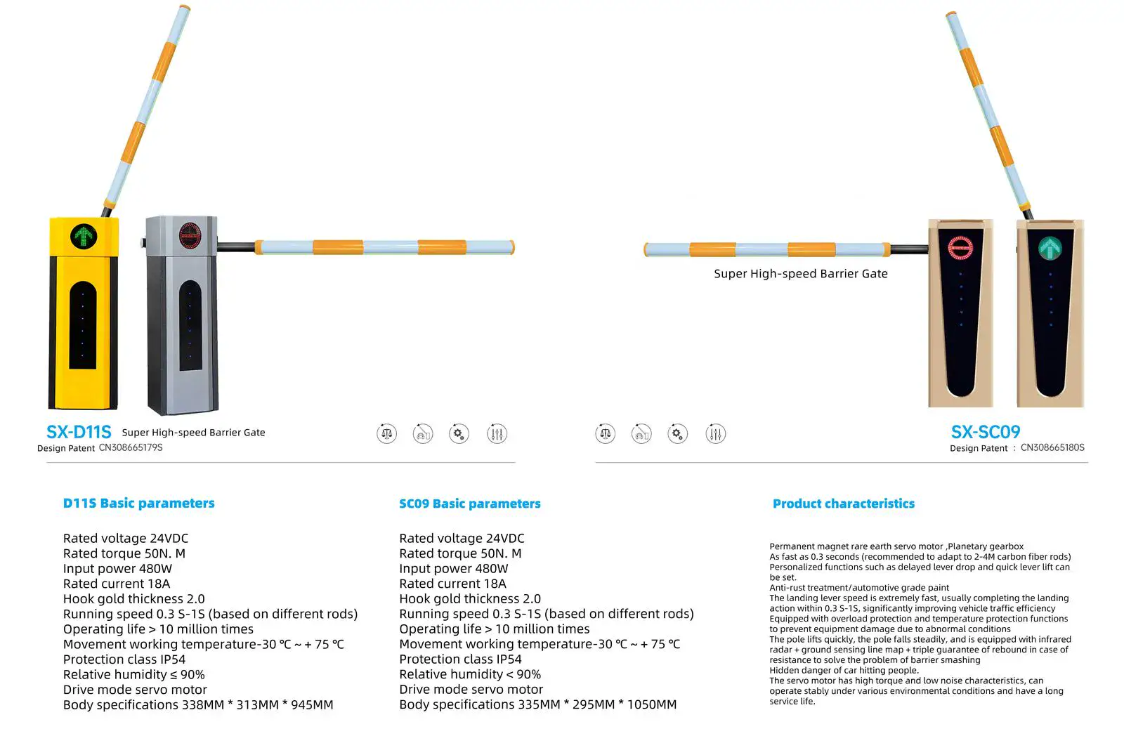
Measure opening and closing time with a stopwatch — not from the datasheet, from the lane. Models in our range are adjustable rather than fixed: the SC02 opens or closes in 1.5–6 s depending on setting, the intelligent series runs from 0.9 s to 6 s, and a servo high-speed model with a 24 V DC drive and a 480 W motor reaches 0.3–1 s. The number that matters is the one the site actually needs for its peak queue, recorded so that "it got slower" becomes a measurable claim later.
Then run a repeatability test: at least twenty consecutive open/close cycles, and note:
- Whether the arm stops at the same position every cycle, or creeps and re-corrects.
- Whether the mechanical limit positions repeat, or whether the controller is hunting for them.
- Abnormal noise, vibration or heat at the cabinet after the run.
- The starting value of the controller's cycle counter, if it has one. That number is the baseline for the entire service plan that follows.
Twenty cycles is not an endurance test; it is a trend test. Surge-protection and overheating problems, arm droop and limit drift all tend to show up in the first twenty movements of a newly installed lane, in quiet conditions, rather than on the first busy Monday.
Electrical acceptance: measure it live, not on paper
The electrical layer is where "it worked yesterday" turns into an intermittent fault, so measure it under load:
- Supply voltage at the cabinet, while the motor runs. Record the reading at rest and the reading during the opening stroke. A supply that reads correctly with the drive idle and sags when the motor starts points to undersized cable or a shared circuit, not to a defective gate.
- Correct configuration for the site's grid. Our barrier gates are built with AC 110–240 V, 50/60 Hz operating voltages and are set at the factory for the destination grid; confirm the delivered controller matches the site rather than assuming it does. Sites with 220–230 V single-phase supply and 60 Hz or 50 Hz service both exist, and the setting is part of the acceptance record.
- Dedicated protection and isolation. The lane should have its own protective device and a means of isolation that a technician can lock off. Confirm the device rating, and confirm nobody has "temporarily" wired the gate onto a lighting circuit.
- Earthing and bonding. Protective earth continuity to the cabinet, verified rather than assumed — it is the reference for every measurement taken afterwards.
- Ingress sealing. Cable entries sealed, gland plates fitted, gaskets intact. Our housings are built to IP54 or IP65 depending on model; that rating applies to a closed cabinet, and an unsealed cable entry defeats it.
- Surge exposure. On open sites, long overhead runs or sites with a history of equipment loss, confirm whether surge protection is present at the lane and note it in the record.
Write the readings down with the instrument used. A voltage figure without a date, a load condition and a measuring point is not evidence.
Detection tests: one device at a time, then as a sequence
Test every detection device separately first, using something that behaves like a vehicle:
- Presence loop: a vehicle standing over the loop must hold the arm open. Test with an actual vehicle, positioned where a car stops — not by pressing a hand or a tool on the surface.
- Pulse or trigger loop: passing over the loop should produce one clean open command, not a burst of commands.
- Safety loop: a vehicle or obstruction in the closing path must stop and reverse the arm. Repeat the test from both the entry and exit side if the lane is shared.
- Photocells and light curtains: break the beam deliberately during the closing stroke. Then check alignment twice — once in the light conditions of the day, once after cleaning the lenses, because damp and dust are what shift a marginal alignment.
- Radar or microwave detectors: confirm the field covers the lane and does not reach into the road or the pedestrian path behind the barrier.
Then test the sequence rather than the parts: a vehicle arrives, the trigger fires, the arm opens before the vehicle reaches it, the presence loop holds the arm, the vehicle clears, the loop releases and the arm closes. Repeat it back to back five times with real vehicles in the queue. The loop detector guide covers device-level diagnosis and the safety sensor guide covers device selection; what commissioning adds is the recorded, repeated sequence test.
Finally, record the settings: detector sensitivity, presence or pulse mode, and any DIP switch or menu position changed on site. Settings changed without a record are the single most common reason a lane "goes wrong" after a service visit.
Access-control, payment and licence-plate sign-off
Integration tests fail quietly. Verify each of these with the integrator present and, where possible, with the vendor's own test card or record:
- Dry-contact inputs: open, close and stop commands each wired and tested individually. One correct open input tells you nothing about the stop input until you use it.
- Relay output behaviour: confirm the relay pulse width is long enough for the controller to accept repeatedly, and whether the contact is normally open or normally closed — the setting must match the integrator's expectation, not the installer's guess.
- Serial or network interface: RS-485 or RS-232 and TCP/IP links used for status, ticketing or camera integration should be tested with the actual software that will run the site, including a restart of that software. Our control boards expose standard dry-contact relay inputs alongside RS-485 communication, with TCP/IP and Wiegand options depending on the lane design.
- Licence-plate trigger timing: the camera reads the plate, the platform decides, the relay fires, the arm starts rising — all before the driver has to stop. Test the worst case (a plate that needs a second read), not the best one.
- Payment and ticket release: validate a real ticket or payment transaction and confirm the release signal reaches the gate and that the exit loop then permits the car to leave. Test the abandoned-transaction case as well.
- Anti-passback: one credential, one vehicle. Attempt a tailgate entry behind an authorised car and confirm the lane either holds the arm or records the event as configured.
- Remotes and credentials: learn one remote or tag of each type the site will use, then delete one, and confirm the count of stored credentials matches the handover list. Also check that the receivers are not picking up a neighbouring site's transmitters.
The LPR integration guide covers wiring and protocol detail, and the ANPR network design guide covers the IT layer; commissioning should end with a signed statement that the interfaces, addresses and trigger modes are as designed.
Safety tests that must pass before you sign
These are not optional and they are not negotiable against a deadline:
- Obstacle reaction. With the arm closing, introduce a test obstacle of representative mass and confirm the arm stops and reverses. Repeat it several times, and confirm the behaviour is consistent rather than occasional.
- Photocell and safety-edge function during the closing stroke, tested with the drive powered and the lane in normal mode — not in a service or learn mode.
- Manual release. Operate it with the drive powered, and again with the power off. Confirm the key or handle is stored on site and that two people on the site know where.
- Emergency opening. Where fire or emergency access applies to the site, confirm the lane's emergency behaviour is the one that was specified, and test it. Our guide to fire department access covers what US sites have to demonstrate, and UL 325 explains the entrapment-protection expectations behind these tests for US projects; in the EU, the equivalent duties sit with EN 12453 in use and EN 12978 for the safety devices themselves.
- Signage and markings. Warning signage installed, keep-clear markings still visible, no pedestrian route through the sweep of the arm, and nothing stored behind the cabinet that blocks the release.
If the site operates the lane before these tests are recorded, the acceptance record is a fiction, and liability for the first incident sits with whoever signed.
Power-loss, battery and emergency access: the test most sites skip
Pull the supply — deliberately, with the lane clear and the operator watching — and record exactly what happens in each of the two cases:
- Arm down, power lost. Does the lane fail safe (arm stays down, traffic diverted) or fail open (arm rises, traffic flows)? Whichever it is, somebody must have chosen it on purpose.
- Arm up, power lost. Does the arm stay up, drop, or sit until the standby source takes over?
- Standby supply. If a battery or UPS backs the lane, time how long it holds and how many cycles it delivers — that number is what the site will rely on during the next outage. Battery-backup sizing and behaviour are covered in the backup power guide.
- Emergency access. Confirm the procedure the site will follow at 2 a.m., including who holds the key.
Documentation and spares to collect at handover
Ask for the pack before the final payment, because after it, requests slow down:
- Wiring diagram and terminal assignment for the exact controller delivered.
- Controller manual, including fault codes or indicator behaviour and the factory default settings.
- Factory quality record — our barrier gates go through multi-stage testing that includes motor performance validation, encoder feedback calibration, cycle endurance testing, extreme-temperature simulation and IP-rated water testing before shipment, and the report is the evidence that your unit was part of it.
- Certificates relevant to your market: ISO 9001 quality management for the plant, CE and RoHS documentation for the equipment, and any market-specific listing your project requires.
- Serial numbers of gate, controller and any cameras or payment terminals, photographed and filed.
- Consumables and spares: fuses, a spare remote or receiver, arm end caps and reflective strips, fasteners, and the correct spare part names so the next email order is unambiguous.
- Warranty terms and the technical support route, with the language the site's technicians actually speak.
Pre-configure at the factory: what belongs in the purchase order
Commissioning is much faster when the order was written properly, because factory pre-configuration replaces site work. When you buy direct, specify:
- Destination grid and frequency (for example 110 V or 220–240 V, 50 or 60 Hz) and the site's phase arrangement.
- Lane width, arm length and whether a folding arm is needed for low clearance.
- Opening direction and handing (left or right).
- Relay output mode and whether loop inputs will be used in presence or pulse mode.
- Interface list: dry contact, RS-485 or RS-232, TCP/IP, Wiegand — as required by the site's access software.
- Remote control frequency, coding type and quantity, plus the language of the labels and manual.
- Spare parts to ship with the first order rather than the second.
Send the site plan, a photo of the entrance and the integrator's interface list with the enquiry — that is enough for a factory to set the unit up for the destination instead of leaving it in a default state that somebody discovers at commissioning.
Conclusion: three things that decide whether the lane survives year one
A new lane is accepted on evidence, not on impressions. The three artefacts that carry that evidence are a measured baseline (travel times, supply readings, detector settings, cycle count at day zero), a completed safety test with the obstacles and the release actually used, and a documentation pack that the site's own technician can act on.
Everything after that — the service interval, the first fault call, the spare-part order — is a comparison against those numbers. Lanes without a baseline are diagnosed by replacement; lanes with one are diagnosed by measurement, which is cheaper for everyone involved.
If you are specifying or importing barrier gates and want the lane delivered pre-configured for your destination grid, arm length and interface list, send the site details and we will come back with a factory-direct configuration for the project.
| Acceptance stage | What is tested | Evidence to keep |
| Mechanical | Cabinet level, foundation, arm length and side, spring balance, fasteners, drainage | Balance check result, bolt torques, photos |
| Electrical | Supply voltage at rest and under load, protective device and isolation, earthing, cable entries | Readings with instrument, date and measuring point |
| Local control | Buttons, remote, manual release, opening and closing time, limit positions, 20-cycle run | Travel times, cycle counter value at day zero |
| Detection | Presence loop, pulse loop, safety loop, photocells and radar, each device then the full sequence | Detector settings plus five repeated sequence runs |
| Integration | Open, close and stop inputs, relay mode, RS-485 or TCP-IP link, LPR trigger, payment release, anti-passback | Interface list signed by the integrator |
| Safety | Obstacle reversal, photocell during closing, manual release powered and unpowered, emergency opening, signage | Signed safety test using a real test obstacle |
| Handover | Training, keys, manual release location, documentation pack, spares, warranty registration | Document pack list, serial numbers, open snag list |
FAQ
How long does commissioning a barrier lane take?
For one lane with a finished power supply and detection already installed, the mechanical, electrical and detection tests are typically about half a day of site work. Add the integrator's time for access-control, payment or camera testing, and expect one further visit if the site is handed over before the electrical work is complete.
Who should carry out the commissioning tests?
A qualified technician for the mechanical, electrical and safety tests, the access-control integrator for the integration tests, and the site operator present for the safety tests. Site staff should not be asked to test entrapment protection or to adjust the balancing spring.
Which instruments should be on site for the acceptance test?
A digital multimeter, a clamp meter for load current, a stopwatch, a tape measure, a torque wrench for anchor and hub bolts, a test obstacle of representative mass, and the factory wiring diagram for the exact controller delivered.
Can we accept the lane if the manual release has not been tested?
No. Manual release and emergency opening behaviour are the functions the site relies on during a power failure, and they are among the most common findings in a first service visit. Test them with the drive powered and again with the power off before signing.
What is the most common commissioning mistake?
Recording the settings nowhere. Detector sensitivity, relay mode and controller parameters changed on site without being written down turn every later fault into a guess. Keep a settings sheet together with the test record.
Which documents should we insist on at handover?
The wiring diagram and terminal assignment for the delivered controller, the controller manual with fault codes and factory defaults, the factory quality record, warranty terms, equipment serial numbers, and a spare parts list that uses the correct part names.
Get a Factory-Direct Quote
Send your project details — lane width, traffic volume and site photos — and our engineering team will reply with a specification, lead time and factory-direct quotation.